
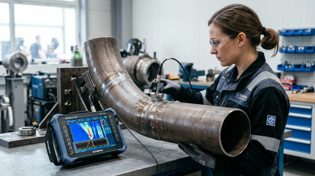
In heavy fabrication, energy plants, oil and gas pipelines, and pressure vessel manufacturing, weld joint integrity directly dictates asset reliability and human safety. For decades, Radiographic Testing (RT) using radioactive isotopes (Iridium-192, Selenium-75, or Cobalt-60) and industrial X-ray tubes served as the industry’s default baseline. However, ionizing radiation hazards, costly plant shutdowns triggered by mandatory exclusion boundaries, and the fundamental constraint of two-dimensional shadow projections have driven a decisive transition toward Phased Array Ultrasonic Testing (PAUT).
As detailed in our foundational guide on Carbon Equivalent (CE) Calculation and Weldability Analysis, alloy steels and heavy structural welds carry heightened susceptibility to hydrogen-assisted cold cracking (HACC) and tight sidewall fusion flaws. Detecting these critical planar discontinuities demands high-resolution volumetric imaging, making PAUT the leading modern non-destructive testing (NDT) methodology worldwide.
Working Principles of Phased Array Ultrasonic Testing (PAUT)
Conventional ultrasonic testing (UT) utilizes a single piezoelectric crystal mounted on an angled wedge to inject acoustic waves into the test piece at a fixed angle (typically 45°, 60°, or 70°). Scanning across varying depths and bevel angles requires repetitive manual raster scanning and frequent wedge swaps.
In contrast, Phased Array Technology integrates an array of multiple small, individually controlled piezoelectric elements (commonly 16, 32, 64, or 128 elements) within a single compact probe housing. Each element is pulsed independently using precise microprocessor-controlled nanosecond timing sequences known as delay laws (or focal laws).
Governed by the Huygens-Fresnel wave superposition principle, the acoustic wavelets emitted by individual elements interfere constructively and destructively, synthesizing a single steerable wavefront. This enables electronic beam steering across a continuous angular sweep and dynamic focal depth control without any physical probe repositioning, delivering unmatched volumetric coverage.

PAUT Scan Formats and Multi-Dimensional Data Visualization
While conventional UT requires manual interpretation of transient oscilloscope signal peaks, PAUT equips inspection engineers with comprehensive multi-view cross-sectional representations of the component interior:
- A-Scan (Amplitude vs. Time-of-Flight): The fundamental raw RF waveform plot displaying reflected echo energy and sound transit time through the material.
- B-Scan (End-View / Cross-Sectional View): A cross-sectional profile along the probe scan travel path, illustrating defect depth and through-thickness positioning.
- C-Scan (Plan / Top-Down View): A two-dimensional planar mapping displaying ultrasonic indications viewed from the inspection surface, ideal for corrosion mapping and composite delamination tracking.
- S-Scan (Sectorial / Azimuthal Scan): The signature display format of PAUT. While holding the probe stationary relative to the weld centerline, the acoustic beam sweeps through an angular sector (typically 40° to 70°). When superimposed over the actual weld bevel overlay, it pinpoints defect geometry in true spatial coordinates.
- D-Scan (Side Profile View): A side projection along the weld longitudinal axis showing defect length and depth distributions.
Comprehensive Comparison: PAUT vs. Conventional Radiographic Testing (RT)
The technical, operational, and safety distinctions between Phased Array UT and conventional industrial radiography are summarized below:
| Evaluation Criteria | Phased Array Ultrasonic Testing (PAUT) | Conventional Radiographic Testing (RT) |
|---|---|---|
| Physics / Radiation Type | High-frequency mechanical acoustic waves (0.5 – 15 MHz) | Ionizing electromagnetic radiation (X-rays & Gamma sources) |
| Health, Safety & Environment | Zero radiation hazard; 100% safe for operators and surroundings | Severe radiological hazard; requires dosimeters and barricades |
| Production Continuity | Zero disruption; adjacent fit-up, welding, and erection continue | Extensive exclusion zone; often restricted to night shifts |
| Planar Defect Detection | Superior sensitivity to tight cracks and sidewall lack of fusion | Poor probability of detection if crack is misaligned to radiation beam |
| Flaw Sizing Capabilities | Direct measurement of length, depth, and through-wall height (h) | Two-dimensional projection only; no through-wall height data |
| Inspection Speed & Reporting | Instant digital acquisition via encoder; real-time onsite analysis | Time lag from chemical film development or CR/DR image scanning |
| Environmental & Waste Profile | Eco-friendly; zero chemical or radioactive waste (water-based gel) | Radioactive isotope disposal, transport licenses, darkroom effluent |
| Applicable Codes & Standards | ASME Sec V Art 4 / Code Case 2235, ISO 13588, ISO 19285 | ASME Sec V Art 2, ISO 17636, EN 1435 |
Decisive Operational and Technical Advantages of PAUT Over RT
Zero Radiation Hazard and Uninterrupted Plant Productivity
The primary economic drawback of industrial radiography in fabrication shops and turnaround projects is the mandatory radiation exclusion perimeter. Conducting gamma radiography requires barricading a 50 to 100-meter radius, halting all concurrent welding, pipefitting, and structural tasks. PAUT relies exclusively on non-hazardous sound waves, allowing inspection personnel to scan girth welds directly adjacent to active workstations without interrupting project schedules or imposing costly night-shift premiums.
Superior Probability of Detection for Planar Flaws and Lack of Sidewall Fusion
Radiography operates on the Beer-Lambert attenuation principle: missing material mass creates greater radiation transmission, darkening the silver halide film. While volumetric defects like spherical porosity or slag inclusions generate readily visible optical contrast, tight planar defects like lack of sidewall fusion or cold cracks do not alter volumetric thickness unless the beam angle aligns within roughly 5° of the flaw plane. PAUT sweeps high-frequency shear waves across multiple calibrated angles, impinging normal to the weld bevel preparation to capture specular reflections and crack-tip diffractions with high reliability.
True Flaw Sizing and Fitness-For-Service (FFS) Compatibility
Radiographic film provides only a two-dimensional silhouette, showing flaw length and projected width while offering no indication of depth or vertical through-wall extent. Modern structural integrity frameworks like API 579-1 / ASME FFS-1 and BS 7910 rely on fracture mechanics to assess whether an indication poses imminent failure risk. Critical acceptance decisions mandate knowing true flaw height (through-wall dimension `h`). PAUT resolves flaw tip diffraction signals to measure both upper and lower crack tips with sub-millimeter precision, eliminating unnecessary and metallurgically damaging repair cutouts.
Full Digital Traceability and Auditable Inspection Archives
Utilizing magnetic wheel scanners linked to optical position encoders, PAUT records positional coordinates synchronized with raw ultrasonic waveforms along 100% of the weld seam. The resulting comprehensive digital dataset serves as an auditable digital twin under ISO 3834 and ASME codes. Decades later, quality auditors can reopen the raw inspection file, reposition virtual gates, verify calibration sensitivities, and track defect growth over consecutive service intervals without risking photographic film degradation or physical archival loss.
Governing Industry Codes and Standardization
The formal replacement of radiography by automated and semi-automated phased array ultrasonic testing is codified across premier global engineering standards:
- ASME Boiler & Pressure Vessel Code Section V, Article 4 & Code Case 2235: Authorizes the use of computer-recorded ultrasonic examination in lieu of radiography for welded pressure equipment.
- ISO 13588: Specifies procedures and equipment standards for the automated phased array ultrasonic testing of metallic weld joints.
- ISO 19285: Establishes standardized acceptance levels and flaw evaluation thresholds for phased array weld examination.
- API 1104 Annex D: Details requirements for mechanised ultrasonic inspection of pipeline girth welds in oil and gas infrastructure.
Sources and References
This technical analysis references official engineering standards and leading non-destructive testing documentation:
- TWI Global – What is Phased Array Ultrasonic Testing (PAUT) and How Does it Work?
- Baker Hughes Waygate Technologies – What is Phased Array Ultrasonic Testing (PAUT)?
- Evident Scientific (Olympus IMS) – Advanced Phased Array NDT Solutions and Inspection Standards
- NDT Connect – RT vs PAUT: Cost, Speed, Detection Decision Matrix & ASME Standards
- Inspecting Pressure Equipment Welds Without Radiation (PAUT Explained)