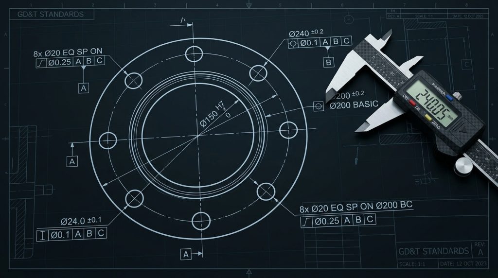
In mechanical design, CNC machining, pipe flange fabrication, and robotic wheel hub design, distributing mounting holes equally along a circular pitch diameter is a daily engineering requirement. Whether manually laying out holes on a drill press with calipers or programming circular Cartesian interpolation in CNC G-code, mastering the trigonometric relationships between Pitch Circle Diameter (PCD / BCD), number of holes ($N$), central angle ($ heta$), and chord length ($C$) is fundamental.
Core Trigonometric Formulas
1. Central Angle Between Adjacent Holes ($ heta$)
θ = 360° / N
Where $N$ is the total number of equally spaced holes.
2. Chord Length / Hole-to-Hole Center Distance ($C$)
The straight-line linear distance between the centers of two adjacent holes across a Pitch Circle Diameter ($D$) is:
C = D * sin(180° / N)
3. Arc Length Along the Pitch Circle ($S$)
The curved distance measured along the circumference between hole centers:
S = (π * D * θ) / 360°
Quick Reference Table for Standard Bolt Counts ($D = 100 ext{ mm}$ Baseline)
| Number of Holes ($N$) | Central Angle ($ heta$) | Chord Factor ($k = \sin(180/N)$) | Hole-to-Hole Distance ($D = 100 ext{ mm}$) |
|---|---|---|---|
| 3 | 120.00° | 0.8660 | 86.60 mm |
| 4 | 90.00° | 0.7071 | 70.71 mm |
| 5 | 72.00° | 0.5878 | 58.78 mm |
| 6 | 60.00° | 0.5000 | 50.00 mm (Exactly equal to Radius!) |
| 8 | 45.00° | 0.3827 | 38.27 mm |
| 12 | 30.00° | 0.2588 | 25.88 mm |
Calculating Cartesian (X, Y) Coordinates for CNC Milling
For CNC machining with the bolt circle centered at $(X_0, Y_0)$ and Radius $R = D/2$, the coordinates of the $k$-th hole ($k = 0, 1, \dots, N-1$) are:
X_k = X_0 + R * cos(k * θ)
Y_k = Y_0 + R * sin(k * θ)