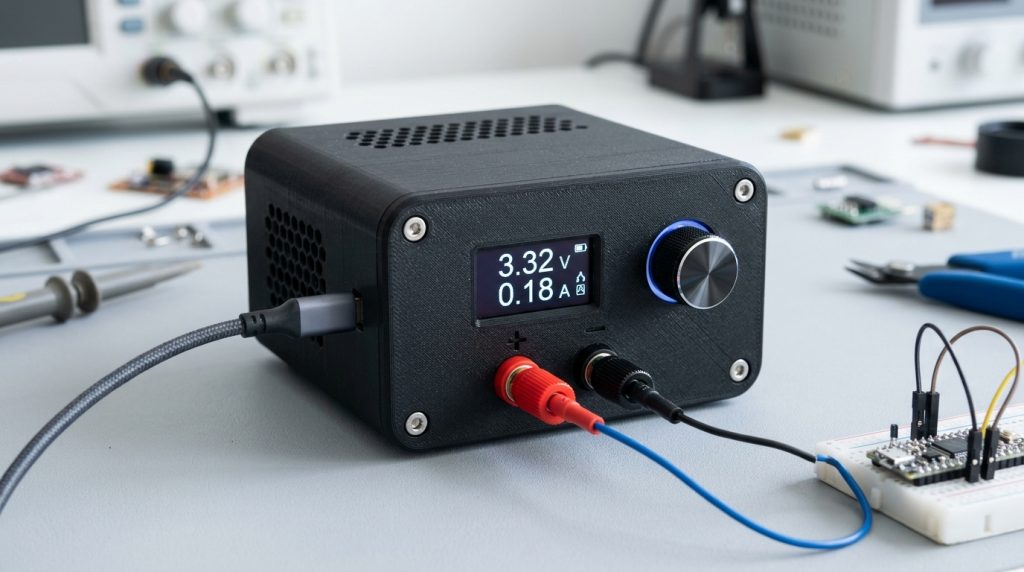
Traditional benchtop DC power supplies are bulky, heavy, and tethered to mains AC transformers. However, the modern USB-C Power Delivery (PD 3.0) and Programmable Power Supply (PPS) ecosystem allows standard GaN phone and laptop chargers to deliver up to 100W (or 240W in USB PD 3.1 Extended Power Range). By controlling the USB PD PHY with an affordable ESP32, you can construct an ultra-compact, digitally regulated, and pocket-sized workshop power supply delivering 3.3V to 21V in 20 mV increments.
For microcontroller firmware fundamentals, explore our ESP32 Setup Guide, and discover enclosure fabrication techniques in our 3D Printing & Slicing Calibration articles.
Understanding USB-C PD 3.0 and PPS Architecture
Standard USB Power Delivery negotiates fixed voltage profiles (5V, 9V, 12V, 15V, 20V). The Programmable Power Supply (PPS) extension allows the sink device to request arbitrary voltages between 3.3V and 21V in precise 20 mV steps, while dynamically adjusting current limits in 50 mA increments:
- CC Communication: Communication takes place over the USB-C Configuration Channel (CC1/CC2) pins using Biphase Mark Coding (BMC) at 300 kHz.
- Hardware Controller Options: While fixed decoy chips (CH224K, IP2721) only trigger fixed 9V/12V/20V rails, true programmable supplies require a bidirectional I2C PD controller such as the FUSB302B, AP33772, or STUSB4500.
- High-Side Sensing: An INA219 or INA226 precision I2C voltage/current monitor measures output voltage and real-time load current across a 0.01 Ω shunt resistor.
Hardware Schematic and Component Selection
| Component | Recommended Part | Role in Circuit |
|---|---|---|
| Microcontroller | ESP32-C3 SuperMini or XIAO ESP32-C3 | Controls user UI, rotary encoder, and runs the PD state machine. |
| USB PD Sink Controller | Diodes Inc. AP33772 (I2C) | Negotiates PPS packets with the GaN charger over CC pins. |
| Current / Voltage Monitor | Texas Instruments INA226 | 16-bit high-side sensing, 0.1 mA resolution, I2C interface. |
| Display | 0.96″ SSD1306 128×64 OLED | Real-time voltage, current, power (Watts), and setpoint display. |
| User Input | EC11 Rotary Encoder with Push Button | Step voltage adjustment and output enable toggle. |
| Output Protection | Low-RDS(on) P-Channel MOSFET + TVS Diode | Reverse voltage and inductive load spike protection. |
Arduino Firmware Implementation with AP33772
Below is a functional Arduino sketch demonstrating how to negotiate a variable voltage setpoint with an AP33772 sink controller over I2C:
#include <Wire.h>
#include <Adafruit_SSD1306.h>

#define AP33772_ADDR 0x51
#define OLED_ADDR    0x3C

Adafruit_SSD1306 display(128, 64, &Wire, -1);
uint16_t target_millivolts = 5000; // Start at 5.0V

void setPPSVoltage(uint16_t mv) {
  // AP33772 PPS Voltage request: 20mV per LSB
  uint16_t pps_code = mv / 20;
  Wire.beginTransmission(AP33772_ADDR);
  Wire.write(0x31); // PPS Voltage Target Register
  Wire.write(pps_code & 0xFF);
  Wire.write((pps_code >> 8) & 0xFF);
  Wire.endTransmission();
}

void setup() {
  Wire.begin(8, 9); // ESP32-C3 SDA, SCL
  display.begin(SSD1306_SWITCHCAPVCC, OLED_ADDR);
  display.clearDisplay();
  display.setTextColor(WHITE);
  display.setTextSize(1);
  display.setCursor(0, 0);
  display.println("ESP32 USB-C PD Supply");
  display.display();
  delay(1000);
  setPPSVoltage(target_millivolts);
}

void loop() {
  // Read rotary encoder and update target_millivolts...
  display.clearDisplay();
  display.setCursor(0, 10);
  display.setTextSize(2);
  display.printf("%.2f V", target_millivolts / 1000.0);
  display.display();
  delay(100);
}