Addressable RGB and RGBW LED strips such as the WS2812B, SK6812, and WS2815 are the gold standard for custom DIY lighting, smart ambient backlights, and Home Assistant automations. Driven by powerful firmware like WLED or ESPHome, an ordinary ESP32 can control hundreds of individual lighting zones. However, nearly every maker eventually encounters the classic triad of frustrating stability bugs: random color flickering, frozen animations, and sudden ESP32 brownout reboots.
While software bugs are often blamed, these problems almost always stem from two fundamental hardware mismatches: logic level voltage thresholds and electrical power bus transients. In this guide, we break down the physics behind these failures and walk through the definitive, lab-tested hardware solutions.
Root Cause 1: The 3.3V to 5V Logic Threshold Mismatch
The ESP32 is a 3.3V logic device. Its GPIO pins output approximately 3.3V when driven high. In contrast, 5V addressable LEDs (WS2812B, SK6812) require a 5V supply rail. According to the official Worldsemi WS2812B datasheet, the minimum high-level input voltage threshold (V_IH) is defined as:
V_IH (min) = 0.7 × V_DD = 0.7 × 5.0V = 3.5VNotice the problem: The LED expects at least 3.5V to reliably recognize a digital ‘1’, but the ESP32 only delivers 3.3V! On a breadboard over a 5 cm jumper wire, you might get away with 3.3V due to component manufacturing tolerances. But as soon as you connect a 1-meter data cable, line capacitance and resistance drop the signal below 3.2V, causing missing timing bits, random green/white flash bursts, and frozen animations.
Why Cheap Bi-Directional I2C Level Shifters Fail
Many beginners attempt to solve this with ubiquitous 4-channel bi-directional level shifters (BSS138 FET-based with 10 kΩ pull-ups). These modules are designed for open-drain I2C buses running at 100–400 kHz. The WS2812B protocol, however, requires precise high-speed 800 kHz NRZ timing with pulse widths of 400 ns and 800 ns. The high pull-up resistance of I2C shifters rounds off the square wave edges (slow rise time), completely destroying the timing signal!
The Definitive Solution: High-Speed 74AHCT125 / 74HCT244 Level Shifters
To convert 3.3V to a crisp 5V square wave at 800 kHz, you must use a push-pull buffer from the AHCT or HCT logic families (such as the 74AHCT125 quadruple bus buffer or the 74HCT244 octal buffer):
- V_IH Threshold: Powered by 5V, an AHCT chip features a V_IH threshold of just 2.0V, easily interpreting the ESP32’s 3.3V output as a solid high logic level.
- Propagation Speed: Sub-10 ns propagation delays preserve razor-sharp rising and falling edges.
- Damping Resistor: Place a 33 Ω to 68 Ω resistor in series on the data line immediately after the level shifter output to absorb high-frequency line reflections (ringing) along the data cable.
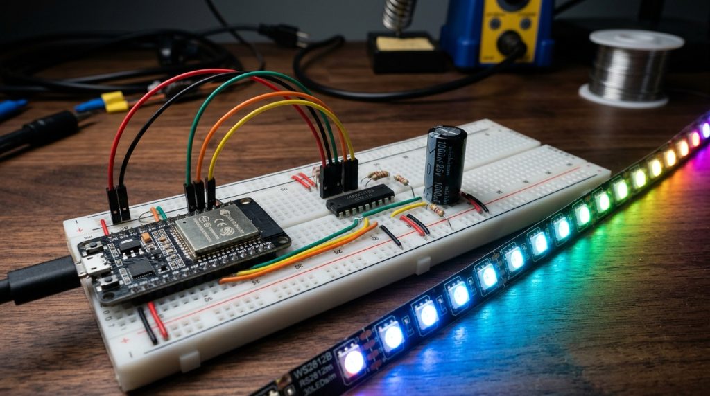
# Wiring Schematic with 74AHCT125
ESP32 GPIO16 ──────────► Pin 2 (1A)
GND ───────────────────► Pin 1 (1OE - Active LOW)
5V Supply ─────────────► Pin 14 (VCC)
GND ───────────────────► Pin 7 (GND)
Pin 3 (1Y Output) ─────► [ 47 Ω Resistor ] ───► LED Strip Data In (DIN)
Quick Hack: The Sacrificial Diode / Sacrificial Pixel Trick
If you don’t have a 74AHCT125 on hand, insert a standard 1N4007 or 1N4148 diode in series with the 5V power line of the first single LED pixel. The diode creates a ~0.7V forward drop, powering the first pixel at ~4.3V. At 4.3V, its input threshold drops to 0.7 × 4.3V = 3.01V, allowing the ESP32’s 3.3V signal to drive it cleanly. That first pixel then regenerates a full 5V logic signal for the rest of the strip!
Root Cause 2: Inrush Currents and Brownout Reboots
A typical 5-meter strip of 60 LED/m WS2812B draws up to 18 Amperes at full white brightness (60 mA per pixel). When animations flash rapidly, the sudden current draw causes a sharp inductive voltage sag on the 5V power bus. If the ESP32 is powered from the same rail, its 3.3V low-dropout (LDO) regulator drops below 2.7V, triggering the hardware Brownout Detector and resetting the chip.
Hardware Power Protection Checklist
- Bulk Electrolytic Capacitor: Place a 1000 µF, 6.3V or 16V low-ESR electrolytic capacitor directly across the +5V and GND terminals where the power supply enters the LED strip. This absorbs instantaneous current spikes.
- Schottky Diode Isolation: Feed the ESP32’s 5V input through a 1N5819 Schottky diode backed by a 470 µF capacitor on the microcontroller side. When the LED rail dips momentarily, the diode prevents the microcontroller capacitor from draining into the LED strip.
- Power Injection: Due to PCB copper trace resistance, never power more than 150 LEDs from a single end. Inject +5V and GND every 2 to 3 meters (and at both ends) using dedicated 18–16 AWG power cables.