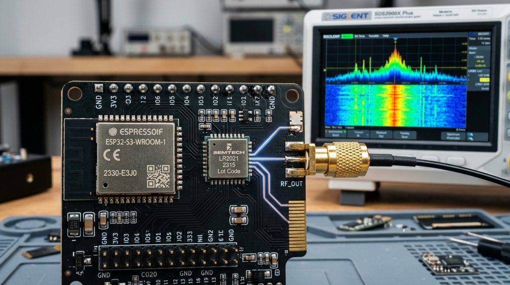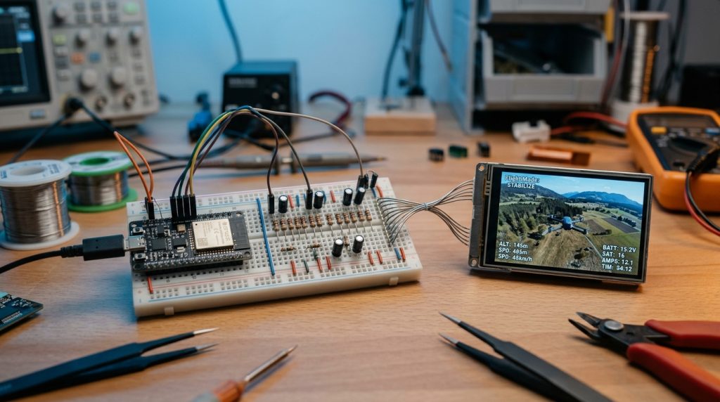
The ESP32 family of microcontrollers is globally renowned as the workhorse of connected DIY electronics and commercial IoT devices. While developers usually rely on it for everyday WiFi and Bluetooth connectivity, recent reverse engineering breakthroughs by the open-source hardware community have uncovered an undocumented capability buried inside the silicon: Direct access to raw I/Q baseband samples right from the integrated RF front-end. This revelation effectively transforms an ordinary ESP32 into a low-cost Software Defined Radio (SDR) receiver.
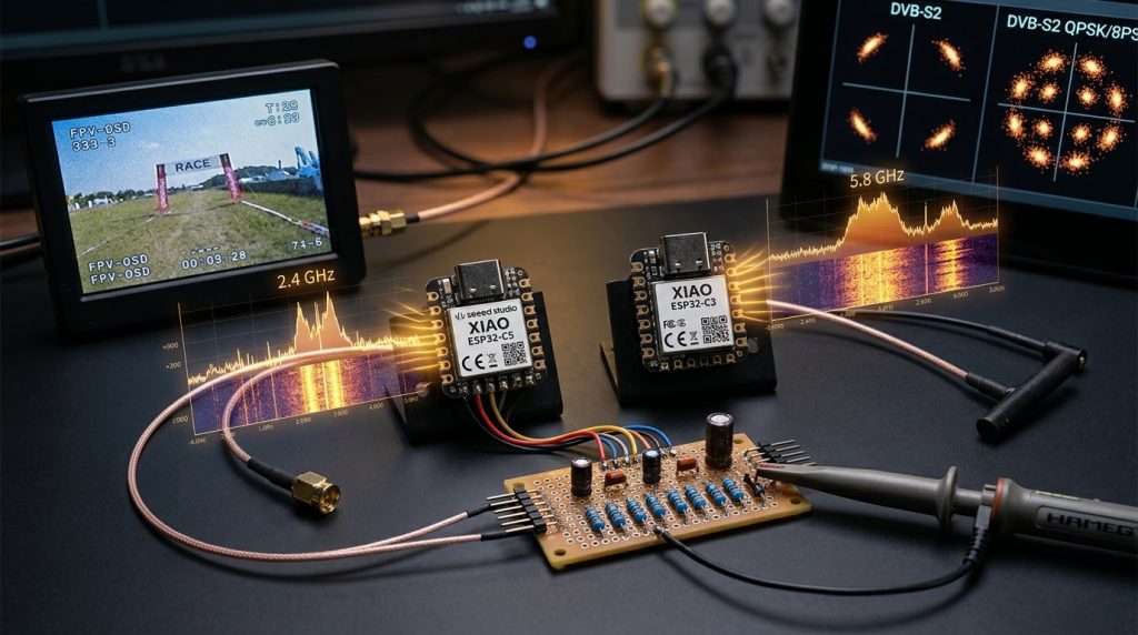
Taking this breakthrough to the next level, developers have leveraged the dual-band ESP32-C5 to capture and demodulate 5.8 GHz analog FPV (First Person View) drone video signals in real time. In this technical guide, we explore how this undocumented SDR mechanism operates, how 5 GHz analog drone video is extracted, and how to build the required hardware output stage.
Raw I/Q Baseband Sampling Inside the ESP32
In conventional ESP32 operation, the radio frequency stage captures incoming 2.4 GHz or 5 GHz RF signals, mixes them down to intermediate frequencies, filters the stream, and feeds it directly into proprietary hardware modems. High-level frameworks, including standard environments detailed in our ESP32 Arduino Setup Guide, only ever interact with formatted network frames.
However, recent low-level register exploration revealed that the balanced In-phase (I) and Quadrature (Q) streams coming off the analog-to-digital converters (ADCs) can be intercepted before reaching the modem block and routed directly into DMA buffers. Much like a dedicated RTL-SDR receiver, this provides developers with unrestricted access to raw spectral slices across supported bands.
Why Analog 5.8 GHz Video Remains Crucial for FPV Drones
Despite the proliferation of high-definition digital transmission systems, 5.8 GHz analog FM video transmission remains the gold standard in competitive drone racing and freestyle aerobatics due to three fundamental characteristics:
- Near-Zero Glass-to-Glass Latency: Without compression or buffering pipelines, frames reach the receiver with sub-millisecond delays.
- Graceful Degradation: When signal strength drops, pilots observe analog static (snow) rather than sudden digital freeze-frames or total disconnection.
- Ultra-Lightweight Transmitters: Simple video transmitters (VTX) deliver substantial RF output power with minimal thermal mass and battery draw.
ESP32-C5 Architecture and R-2R Resistor Ladder DAC
In community projects such as C5VRX and Twotoz’s demonstrations, the dual-band WiFi 6 ESP32-C5 is deployed to tune directly into the 5.8 GHz FPV video band. The raw FM signal is sampled and demodulated purely in software running on the microcontroller core.
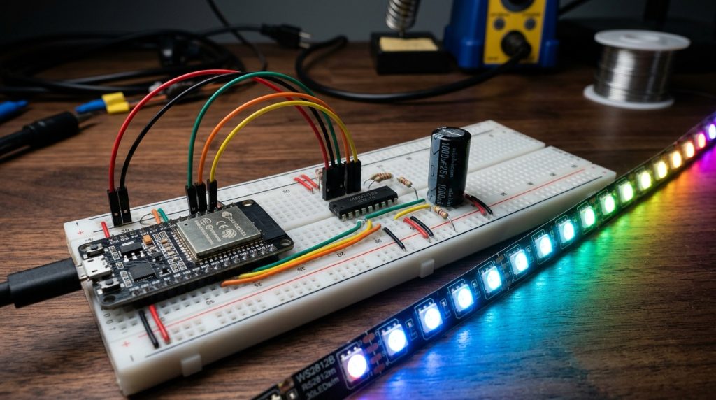
To output the demodulated composite video (CVBS / NTSC / PAL) to a monitor or goggles, an analog signal is required. Because dedicated video DACs add cost and complexity, the project employs a classic R-2R resistor ladder DAC wired across multiple high-speed GPIO pins. This simple passive network converts digital byte streams into accurate video voltage levels with negligible latency.
// ESP32-C5 Raw I/Q DMA Pipeline Initialization (Conceptual ESP-IDF Implementation)
#include "esp_wifi.h"
#include "driver/gpio.h"

void configure_sdr_rx_pipeline(void) {
    // Redirect internal RF receiver into custom I/Q DMA ring buffers
    wifi_promiscuous_filter_t filt = {
        .filter_mask = WIFI_PROMIS_FILTER_MASK_ALL
    };
    esp_wifi_set_promiscuous_filter(&filt);
    esp_wifi_set_promiscuous(true);

    // Tune directly to target 5 GHz FPV carrier (e.g. Channel 1: 5740 MHz)
    esp_wifi_set_channel(1, WIFI_SECOND_CHAN_NONE);
}
Hardware Considerations and Best Practices
When replicating or experimenting with this build, keep the following hardware constraints in mind:
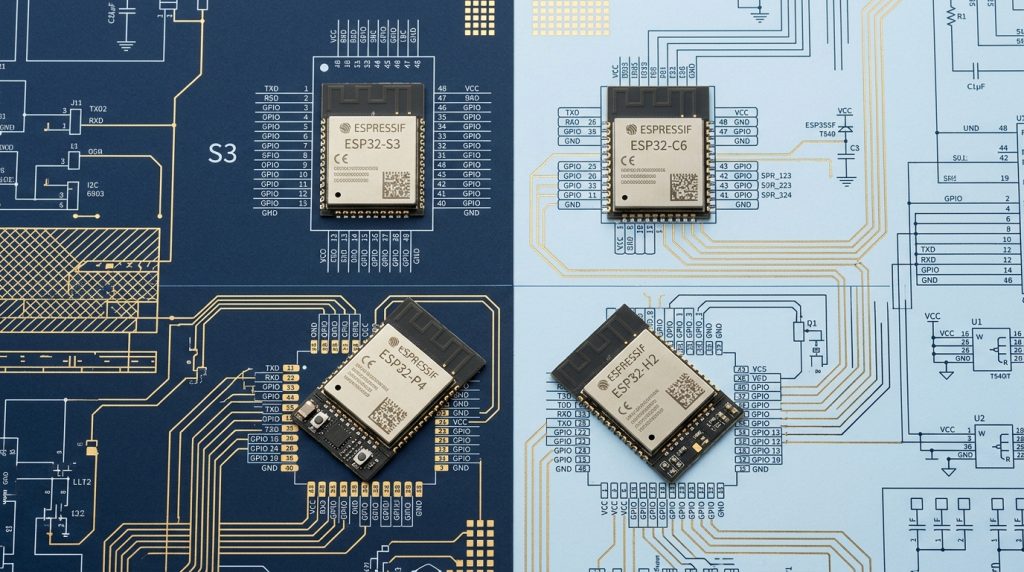
- Silicon Selection: Native 5 GHz reception requires the ESP32-C5 or dual-band equivalents. Legacy ESP32-WROOM and ESP32-S3 modules only cover 2.4 GHz.
- Antenna Matching: Due to severe path loss in the 5.8 GHz spectrum, use a well-matched circular-polarized antenna (such as a RHCP cloverleaf) connected directly to the micro U.FL / IPEX port.
- Power Rail Decoupling: High-speed RF sampling is vulnerable to digital switching noise. Place 100nF and 10uF low-ESR ceramic decoupling capacitors close to the 3.3V power rails.
Limitations and Future Outlook
While running an SDR on an ESP32 is a remarkable engineering feat, it is not a drop-in replacement for laboratory-grade instruments like the HackRF. The instantaneous bandwidth and analog filtering stages remain constrained by the internal WiFi frontend silicon. Nonetheless, unlocking 5 GHz analog video reception on a commodity microcontroller opens exhilarating possibilities for embedded telemetry, RF monitoring, and low-cost ground stations.
We recommend you check out our more recent and comprehensive article, “The Hidden SDR Revolution on ESP32: Spectrum Analysis, 5.8 GHz Drone Camera Monitoring, and DVB-S2 Digital TV Broadcasting with ESPsoup, C5VRX, and ESP32-DATV” 😉
Sources and References
This article was authored with reference to recent engineering disclosures and community projects: