
Every embedded systems and radio frequency (RF) engineer remembers how the discovery of an undocumented raw I/Q streaming mode inside the humble RTL2832U DVB-T TV tuner chip ignited the global RTL-SDR revolution. Today, an equally transformative hardware breakthrough is unfolding across the Espressif ESP32 ecosystem. The ultra-low-cost microcontrollers we routinely deploy for packet-based Wi-Fi and Bluetooth connectivity harbor an undocumented Software-Defined Radio (SDR) baseband signal path originally left in silicon for factory wafer testing and RF calibration.
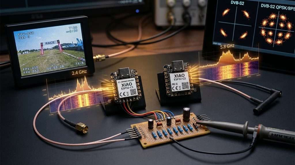
Building upon the foundational discoveries covered in our earlier analyses—Hidden SDR Mode Discovered in ESP32 and LR2021 LoRa Chips: Turning Microcontrollers into Software-Defined Radios and Hidden SDR Capability in ESP32 Hardware and 5 GHz Drone Video Receiver—the open-source hardware community has rapidly created three extraordinary applications: scanning and decoding the 2.4 GHz and 5 GHz spectrum for wireless reconnaissance and live FPV viewing (ESPsoup), receiving real-time 5.8 GHz analog drone video into FPV goggles using just seven passive resistors and zero CPU overhead (C5VRX), and transmitting full DVB-S / DVB-S2 digital television at up to 1 MSymbol/s using a bare $2 ESP32-C3 board (ESP32-DATV).
In this comprehensive guide, we dissect the silicon architecture from the core register level all the way to hands-on implementation so that anyone can understand how the hardware works and build all three projects on their own workbench.
Core Architecture: Is the Hidden ESP32 SDR Mode a Hardware Backdoor?
When news of raw RF capture on the ESP32 first broke, a common question was: “Is there a hardware backdoor in ESP32 chips?” To answer this accurately, we need to trace the internal signal chain of a modern wireless System-on-Chip (SoC):
- RF Analog Front-End: Incoming 2.4 GHz or 5 GHz signals pass through a Low-Noise Amplifier (LNA), are mixed down to baseband by a quadrature mixer driven by an internal Phase-Locked Loop (PLL) synthesizer, and pass through programmable analog baseband filters.
- Internal High-Speed ADC and DAC: The analog I (In-Phase) and Q (Quadrature) baseband signals are digitized by an internal high-speed Analog-to-Digital Converter (ADC) at up to 80 MSa/s. Conversely, on the transmit (TX) path, an internal 10-bit Digital-to-Analog Converter (DAC) drives the RF modulator.
- Fixed-Function Hardware Modem (Wi-Fi / BLE PHY): Under normal operation, firmware never sees raw ADC samples; the fixed-function hardware modem demodulates standard 802.11 or Bluetooth frames and hands only decoded network packets to the CPU.
When the ESPARGOS team (ESP-SDR) and independent researcher h0m3us3r (eSpDR) reverse-engineered the adctrig function inside Espressif’s internal librftest library with the aid of Large Language Models (LLMs), they uncovered undocumented diagnostic registers (MODEM_DIAG and sample-dump engines) left by Espressif engineers for on-wafer factory testing.
Configuring these registers bypasses the fixed-function Wi-Fi modem entirely, routing raw I/Q samples directly into internal SRAM or on-chip hardware peripherals like the BitScrambler. Therefore, this is not a malicious security backdoor—it is an undocumented hardware diagnostic interface that unlocks the chip’s physical radio for arbitrary software-defined radio applications.
32-Bit I/Q Sample Word Format and Two-Bank SRAM Ring Buffer
In the ESPARGOS/esp-sdr implementation, each complex baseband sample written into SRAM occupies one 32-bit word:
- Bits 0 – 9 (10-Bit Signed Q Sample): Quadrature component (
-512to+511). - Bits 10 – 19 (10-Bit Signed I Sample): In-Phase component (
-512to+511). - Bits 20 – 27 (8-Bit Receiver Gain Index): Reports the active index in the hardware receiver gain table.
- Bits 28 – 31 (4-Bit AGC FSM State): Reports the internal state of the hardware Automatic Gain Control (AGC) finite state machine.
Firmware reserves two internal SRAM banks away from the system heap and configures them as a two-bank ring buffer: while the modem writes 80 MSa/s raw I/Q samples into Bank A, the CPU processes or transfers completed samples from Bank B, swapping bank ownership on each pass.
Overcoming the 2.56 Gbps I/Q Throughput Bottleneck
At 80 MSa/s and 32 bits per sample, the modem writes 2,560 Mbit/s (2.56 Gbps) into SRAM—far faster than a standard ESP32’s 12 Mbit/s Full-Speed USB or 80 Mbit/s SPI bus can export continuously. The three projects we examine solve this bottleneck through three distinct architectural strategies:
- ESPsoup (On-Chip Demodulation & Gap-Free Burst Analysis): Computes spectra, classifies RF bursts, decodes public broadcast protocols (BLE, Wi-Fi, Remote ID, Zigbee), and demodulates analog TV video directly on the ESP32-C5, sending only compact spectra, decoded metadata, or demodulated video lines over Native USB.
- C5VRX (Zero-CPU Hardware Peripheral Pipeline): Never moves raw samples over USB or through the CPU at all. It routes 40 MS/s
MODEM_DIAGsamples straight into the ESP32-C5’s hardware BitScrambler for WBFM demodulation and streams 6-bit composite video out through the PARLIO peripheral into a passive resistor DAC. - ESP32-DATV (Direct 10-Bit Wi-Fi DAC Synthesis): Operates in the transmit (TX) direction, receiving compact DVB-S/S2 symbols over USB (or reading pre-encoded video from internal SPI flash), applying a Root-Raised-Cosine (RRC) filter in fast assembly loops, and writing I/Q samples at up to 8 MS/s directly into the ESP32-C3’s Wi-Fi DAC.
Architectural Comparison: ESPsoup vs. C5VRX vs. ESP32-DATV
| Feature / Metric | ESPsoup (espsoup.com) | C5VRX (Twotoz/C5VRX) | ESP32-DATV (SP8ESA/ESP32-DATV) |
|---|---|---|---|
| Primary Role | 2.4 & 5 GHz Pocket Spectrum Analyzer, RF Recon Scanner & Multi-TV FPV Receiver | Ultra-Minimal, Zero-CPU 5.8 GHz Analog FPV Drone Video Receiver (VRX) | 2.4 GHz (13 cm) DVB-S / DVB-S2 Digital Amateur Television Transmitter (TX) |
| Target Chip / Board | ESP32-C5 (Waveshare ESP32-C5-WROOM-1U or Seeed XIAO ESP32-C5) | Seeed Studio XIAO ESP32-C5 | ESP32-C3 (e.g., ESP32-C3 SuperMini, Rev 0.3+, 4 MB Flash) |
| RF Direction | Receive-Only (RX – Never transmits) | Receive-Only (RX) | Transmit-Only (TX – Direct RF synthesis) |
| Frequency Range | 2.13 – 2.73 GHz and 4.79 – 5.99 GHz (Dual-Band) | 5.362 – 5.945 GHz (48-Channel 5.8 GHz Analog FPV Band) | 2.300 – 2.450 GHz (13 cm Amateur Band & QO-100 Uplink) |
| External Components | None (USB-C data cable + Android OTG or PC browser) | 7 Passive Resistors (6-bit binary-weighted DAC + 200 Ω load) | None required for bench test (Bandpass filter & PA for licensed on-air use) |
| Output Interface | Web App (Web Serial in Chrome/Edge) & Android App | Real-Time Analog CVBS (PAL/NTSC) Composite Video for Goggles/Monitors | Over-the-Air DVB-S / DVB-S2 (QPSK, 8PSK, 16APSK, 32APSK) RF Signal |
| License | Firmware: GPL-3.0 (Based on ESP-SDR) | GPL-3.0-only | PolyForm Noncommercial 1.0.0 |
ESPsoup: 2.4 and 5 GHz Pocket Spectrum Analyzer, Wireless Recon, and Multi-TV Receiver
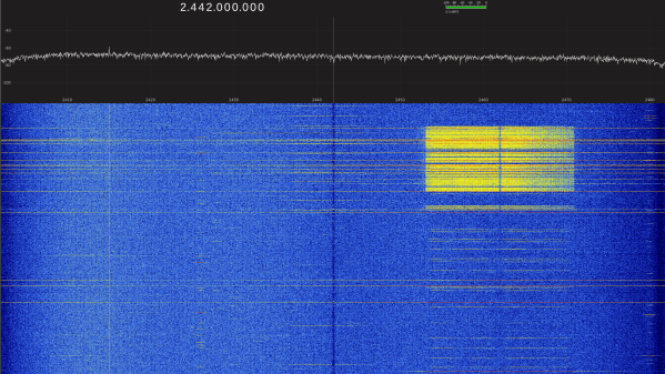
Created by independent German developer Peter Holzhauser, ESPsoup (GitHub: pit711/ESPsoup and pit711/espsoup-firmware) turns a €15–€25 ESP32-C5 development board connected over USB into a pocket radio scanner covering 2.13–2.73 GHz and 4.79–5.99 GHz. As highlighted by RTL-SDR.com, while a standard RTL-SDR stick tops out around 1.766 GHz, ESPsoup covers the exact 2.4 GHz and 5.8 GHz bands where Wi-Fi, Bluetooth, smart home protocols, and FPV drones operate.
Wireless Reconnaissance, Protocol Decoding, and Drone Detection
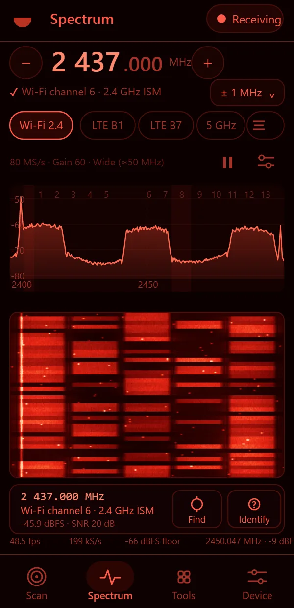
ESPsoup is strictly receive-only (it never transmits) and processes everything locally on your device. Across its four tabs—Scan, Spectrum, Tools, and Device—it provides an extensive wireless reconnaissance toolkit:
- Drone Remote ID & RC Link Classification: Decodes public Drone Remote ID broadcasts (over Bluetooth LE, Wi-Fi Beacon, and Wi-Fi NAN) in both 2.4 GHz and 5 GHz bands, plotting both the drone and pilot positions on a live map. Its burst classifier also recognizes ExpressLRS (ELRS), FLRC, Ghost, Tracer, FrSky, FlySky, DSMX, and digital video links like DJI OcuSync, HDZero, and Walksnail by their spectral shape.
- BLE Sniffing & AirTag / Tracker Warnings: Captures 60–120 BLE packets/second (including BLE 2M and Extended Advertising), decodes smart home sensors (BTHome, Xiaomi, Govee, Ruuvi), and identifies Apple AirTag, Samsung SmartTag, Tile, and Google trackers—alerting you if an unknown tracker keeps moving with you.
- Wi-Fi Auditing & Deauth Detection: Extracts 2.4 GHz and 5 GHz (including channels above 5.75 GHz) network names from beacons, resolves IEEE MAC vendor names, monitors 24-hour channel occupancy, captures ESP-NOW traffic, and detects Wi-Fi Deauthentication attacks.
- Smart Home, Solar Inverters & Automotive V2X: Decodes Zigbee, Zigbee Green Power, and Thread (802.15.4) at 2405–2480 MHz, nRF24 links, Hoymiles solar micro-inverters, 2457 MHz ANT+ sensors, and ITS-G5 / 802.11p car-to-car V2X communications at 5.855–5.925 GHz.
- Hidden Wireless Camera Finder & GPS Heatmap Direction Finding: Scans for continuous 2.4 GHz and 5.8 GHz transmitters, automatically steps down receiver gain in 10 dB increments as you approach the source, offers a “body shadow” bearing mode, and estimates transmitter location on offline OpenStreetMap terrain tiles.
- LTE / 5G NR Cell IDs & Crystal Calibration: Reads LTE and 5G NR cell identities in Bands 1 (2.11–2.17 GHz) and 7 (2.62–2.69 GHz) and uses carrier-grade base station frequencies to calibrate your ESP32-C5 board’s crystal offset.
ESPsoup TV and Multi-TV: Watching Up to 8 Analog FPV Channels Simultaneously
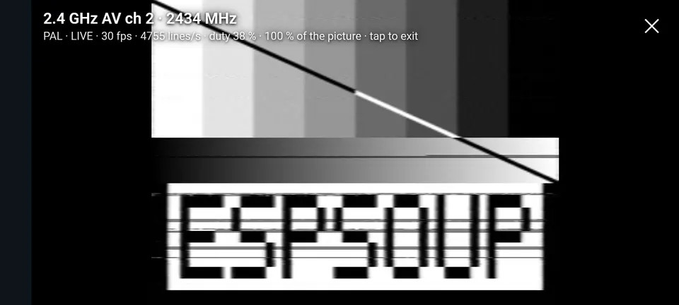
Under Tools → TV, ESPsoup demodulates all 52 receivable analog video channels (Raceband, Fatshark, Boscam A/B/E, Lowband at 5362–5945 MHz, and 2.4 GHz AV at 2414–2468 MHz) directly on the ESP32-C5 at 24–28 fps (~7,900 lines/s) in black-and-white or coarse PAL/NTSC color, complete with WebM recording and 30-second instant replay.
Multi-TV and Why a Multi-TT USB Hub Matters: Because each ESP32-C5 tunes one analog channel at a time, you can plug 8 ESP32-C5 boards into a USB hub to watch an entire band (e.g., Raceband R1–R8) simultaneously. Each board streams video over USB 2.0 Full-Speed (12 Mbit/s). On a cheap Single-TT (Single Transaction Translator) hub, all boards share one 12 Mbit/s (~1.1 MB/s) lane, degrading resolution. Always choose a powered Multi-TT USB hub (using chips like the VIA VL817/VL822 or Realtek RTS5411, such as the StarTech ST4300USB3V2-UE) so every ESP32-C5 gets its own dedicated 12 Mbit/s lane.
Step-by-Step ESPsoup Setup Guide
- Connect via Native USB: Use an ESP32-C5 board with an external antenna connector (such as the Waveshare ESP32-C5-WROOM-1U kit or Seeed Studio XIAO ESP32-C5). Always plug your USB-C data cable into the board’s Native USB port, never the slower UART bridge port.
- Flash ESPsoup Firmware 0.7.1: Open app.espsoup.com in desktop Chrome, Edge, or Opera (or install the Android APK via USB OTG). Navigate to Device → Firmware to automatically back up your flash and install
ESPsoup firmware 0.7.1. - Enable Airplane Mode on Mobile: When scanning on a phone, switch on Airplane Mode so your phone’s own Wi-Fi and Bluetooth transmitters do not swamp the ESP32-C5 antenna located centimetres away.
- Export to Home Assistant via MQTT: Enable MQTT export under the Device tab to stream detected trackers, drone Remote IDs, or spectrum alerts straight into your Home Assistant Open-Source Smart Home server.
C5VRX: Zero-CPU 5.8 GHz Analog FPV Receiver with Seven Resistors and an ESP32-C5
While ESPsoup displays video inside a browser or phone app, FPV drone pilots need a low-latency receiver module that outputs standard analog CVBS (PAL/NTSC) composite video directly into analog FPV goggles or a DVR monitor. Created by Leon (Twotoz), Twotoz/C5VRX (c5vrx.com) replaces scarce traditional RX5808 receiver modules with a single Seeed Studio XIAO ESP32-C5 and seven passive resistors.

How the Zero-CPU MODEM_DIAG to BitScrambler Pipeline Works
As featured on Hackaday and CircuitDigest, the C5VRX-5 firmware keeps the RISC-V CPU completely out of the high-speed sample path:
- Wi-Fi 6 PHY
MODEM_DIAGCapture (40 MS/s): Taps selected bits from the ESP32-C5’s radio ADC at 40 MS/s across all 48 standard 5.8 GHz FPV channels (internal I/Q routing usesGPIO27andGPIO2with no external jumper wires). - Hardware
BitScramblerWBFM Demodulation: Streams samples directly into the ESP32-C5’s hardware BitScrambler peripheral running the U80P64-R1 (or tracking U85Q) wideband FM demodulator, recovering composite video and preserving the original colour burst. PARLIO& 6-Bit Binary-Weighted Resistor DAC: Streams 6-bit composite video samples out of pinsD4–D9via the Parallel IO (PARLIO) peripheral at 40 MHz (TX40, 20 MS/s unique code pairs[D,D]), complete with an on-screen goggle menu (OSD), automatic gain control (LEVEL/KEEL/RSSI), and 48-channel auto-scan.
Building and Testing the 6-Bit Resistor DAC
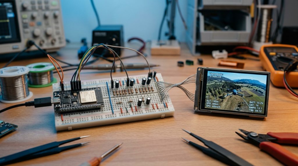
Following the official C5VRX Resistor DAC Build and Test Guide, solder six 1% E24 metal-film resistors to pins D4 through D9 on your Seeed Studio XIAO ESP32-C5, join their free ends together to form the VIDEO output node, and connect a seventh 200 Ω load resistor from that node to GND:
| XIAO Pin | ESP32-C5 GPIO | DAC Bit | Resistor to VIDEO Node (1% E24) | 4-Band Color Code | Expected Multimeter Reading (3.30V Rail, Display Unplugged) |
|---|---|---|---|---|---|
| D4 | GPIO23 | Bit 0 (LSB) | 8.2 kΩ | Grey, Red, Red | ~31 mV |
| D5 | GPIO24 | Bit 1 | 3.9 kΩ | Orange, White, Red | ~64 mV |
| D6 | GPIO11 | Bit 2 | 2.0 kΩ | Red, Black, Red | ~125 mV |
| D7 | GPIO12 | Bit 3 | 1.0 kΩ | Brown, Black, Red | ~251 mV |
| D8 | GPIO8 | Bit 4 | 470 Ω | Yellow, Violet, Brown | ~533 mV |
| D9 | GPIO9 | Bit 5 (MSB) | 240 Ω | Red, Yellow, Brown | ~1044 mV |
| GND | GND | Load Resistor | 200 Ω (VIDEO node to GND) | Red, Black, Brown | ALL High: ~2047 mV / NONE High: 0 mV |
# Flash C5VRX-5 from source using ESP-IDF 6.0.2 (or use the browser flasher at c5vrx.com)
git clone https://github.com/Twotoz/C5VRX.git
cd C5VRX
idf.py build
python tools/flash.py /dev/ttyACM0 --check

# Verify every resistor branch with the built-in DAC self-test (press 'Z' in serial console):
python3 tools/dac_check.py --vdd 3310 --d4 30.8 --d5 64.3 --d6 125.4   --d7 250.9 --d8 529 --d9 1031 --all 2032 --none 0.2
Safety Note: C5VRX is experimental firmware. Always test every firmware and hardware combination on the ground with propellers removed, run CALIBRATE with your VTX off before flying, and never rely on C5VRX as your sole means of maintaining safe aircraft control.
ESP32-DATV and ESP32-DATV-SA: Bare ESP32-C3 DVB-S2 Digital Amateur TV Transmitter
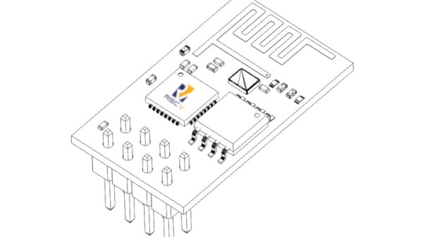
Developed by Polish radio amateur SP8ESA, SP8ESA/ESP32-DATV (Hackaday Coverage and FabScene Analysis) turns a bare ESP32-C3 (such as an ESP32-C3 SuperMini) into a DVB-S and DVB-S2 digital amateur television (DATV) transmitter operating in the 13 cm amateur band (2300–2450 MHz)—including the QO-100 (Es’hail-2) amateur satellite wideband uplink frequencies—with zero external RF modulator hardware!
Direct Wi-Fi DAC Synthesis, RRC Filtering, and 32APSK Performance
On the host PC, FFmpeg encodes a video file or live V4L2 camera feed into a constant-bit-rate MPEG transport stream (TS), applies DVB-S or DVB-S2 framing, and streams symbols over the ESP32-C3’s native USB Serial/JTAG interface. The ESP32-C3 applies a Root-Raised-Cosine (RRC, roll-off 0.35) filter and writes I/Q samples at up to 8 MS/s directly to its internal 10-bit Wi-Fi DAC:
| Modulation | Standard | Supported Symbol Rates (kS/s) | DAC Sample Rate & Measured Spectral Purity |
|---|---|---|---|
| QPSK | DVB-S, DVB-S2 | 33, 66, 125, 250, 333, 500, 1000 kS/s (1 MS/s) | Default amplitude --amp 300; clean decoding up to 1 MSymbol/s. |
| 8PSK | DVB-S2 | 33, 66, 125, 250, 333, 500, 1000 kS/s (1 MS/s) | Default amplitude --amp 420; default GUI profile for QO-100 WB channels. |
| 16APSK | DVB-S2 | 33, 66, 125, 250, 333, 500, 1000 kS/s (1 MS/s) | At 1 MS/s, DAC runs at 8 MS/s (8 SPS); first image peaks are 27–28 dB below carrier. |
| 32APSK | DVB-S2 | 33, 66, 125, 250 kS/s | At 250 kS/s, DAC runs at 8 MS/s (32 SPS); first image peaks are 39.8–40.3 dB below carrier with 0 TS errors! |
PC-Free Operation: The ESP32-DATV-SA Stand-Alone Fork by TA7W (Barış Dinç)
Taking the concept one step further, Turkish radio amateur Barış Dinç (TA7W / OH2UDS) and the yATOLYE community created barisdinc/ESP32-DATV-SA (AMSAT-DL Forum Thread), enabling the ESP32-C3 to transmit DVB-S2 video and test beacons completely standalone without a PC:
- Looping Video Directly from Internal SPI Flash (v0.3.0-sa): Stores up to ~35 seconds of H.264 + MP2 video in a dedicated 2.9 MB partition at flash offset
0x110000. Using background SPI1 reads into a 512-byte RAM ring buffer, it transmits live DVB-S2 QPSK 3/4 video at 330.579 kS/s with a measured 22 dB MER. - Zero-Install Browser Video Converter & OLED Front Panel: Convert any video file into
video.bindirectly inside your browser at barisdinc.github.io/ESP32-DATV-SA/converter/ and flash it via esptool-js. You can also wire an I2C OLED display (GPIO0/GPIO1), EC11 rotary encoder (GPIO5/6/7), and three buttons (GPIO10/20/21) to adjust frequency, output level, symbol rate, and service name on the fly.
Building and Running ESP32-DATV
If you are setting up your Espressif development environment for the first time, check our ESP32 Setup and Configuration Guide. To build and run ESP32-DATV with ESP-IDF 6.2.0 on Linux:
# 1. Clone the repository and flash the ESP32-C3 firmware
git clone https://github.com/SP8ESA/ESP32-DATV.git
cd ESP32-DATV/firmware
idf.py set-target esp32c3
idf.py -p /dev/ttyACM0 build flash
cd ..

# 2. Set up the Python virtual environment and launch the transmitter GUI
python3 -m venv .venv
. .venv/bin/activate
python3 -m pip install -r host/requirements.txt
python3 -m pip install -r host/requirements-gui.txt
./uruchom_nadajnik.sh

# Or transmit DVB-S2 16APSK at 1 MS/s or live V4L2 camera video in 32APSK via CLI:
python3 host/tx_dvbs.py --freq 2370 --baud 1000000 --dvbs2 --mod 16apsk --fec 2/3 --pilots
python3 host/tx_dvbs.py --freq 2370 --baud 250000 --dvbs2 --mod 32apsk --fec 3/4   --pilots --apsk-pl unit --camera /dev/video0 --camera-size 640x480 --camera-fps 30 --camera-format mjpeg
Regulatory & Filtering Notice: The firmware restricts transmission to 2300–2450 MHz. Because the bare ESP32-C3 has no output reconstruction filter, DAC images appear in the spectrum; always use a proper 13 cm bandpass filter and operate strictly within the privileges of your amateur radio license.
Extra Frontier: Controlling 2.4 GHz Toy RC Cars and Drones with ESP32 SDR
Can we use this exact same SDR transmission technique to directly control off-the-shelf 2.4 GHz RC toy cars, boats, or mini drones? The answer is: Absolutely yes!
Commercial 2.4 GHz toy RC vehicles do not use Wi-Fi or Bluetooth; they rely on low-cost RF transceivers such as the nRF24L01 or its popular clones—XN297, XN297L, PanChip (PAN159), and Beken (BK2461). These chips communicate via 250 kbps or 1 Mbps GFSK (Gaussian Frequency Shift Keying) modulation. Previously, controlling these toys required wiring an external SPI nRF24L01 module to an ESP32 because the standard Wi-Fi modem rejected non-802.11 packets.
However, as proven by esp32-sdr-trx and ESP32-DATV, bypassing the Wi-Fi modem and accessing the on-chip DAC transforms the ESP32 into an arbitrary waveform transmitter. By generating synthetic GFSK I/Q vectors from the open-source protocol definitions in the DIY-Multiprotocol-TX-Module repository (binding sequence, throttle/steering bytes, and CRC), an ESP32 can transmit directly to the toy car without modifying the car’s electronics. Moreover, because toys use one-way (simplex) transmission, no fast RX/TX switching is required—and the ESP32’s powerful +19.5 dBm internal PA can double or triple the toy’s original transmitter range!
Sources and References
This article was compiled using the following primary repositories and technical documentation:
- ESPsoup Official Website – ESP32-C5 SDR App, Spectrum Analyzer & FPV Receiver
- GitHub – pit711/ESPsoup & pit711/espsoup-firmware (GPL-3.0)
- GitHub – Twotoz/C5VRX: Ultra-Minimal, Zero-CPU 5.8 GHz Analog FPV Video Receiver on ESP32-C5
- C5VRX Official Web Flasher and Hardware Documentation
- GitHub – SP8ESA/ESP32-DATV: DVB-S / DVB-S2 Digital Amateur TV Transmitter Using a Bare ESP32-C3
- GitHub – barisdinc/ESP32-DATV-SA: Stand-Alone Fork of ESP32-DATV Without a PC (TA7W / OH2UDS)
- ESPARGOS – ESP-SDR: Raw IQ Capture with Espressif’s ESP32 Chips
- RTL-SDR.com – ESPsoup: Turn an ESP32-C5 into a 2.4 & 5 GHz Pocket Scanner
- Hackaday – 5 GHz Drone Video, With An ESP32 (C5VRX)
- Hackaday – Using An ESP32-C3’s RF Hardware For DVB-S2 Video Transmission
- CircuitDigest – Seven Resistors and an ESP32-C5: Open-Source FPV Receiver
- GitHub – jochenhammes/esp32-sdr-trx: Software-Defined Transceiver on ESP32-S3
- GitHub – pascallanger/DIY-Multiprotocol-TX-Module: 2.4GHz Multi-Protocol Transmitter Framework

Pingback: Unlocking Hidden SDR Capabilities in ESP32 Hardware for 5 GHz Drone Video Reception - Karakavuz