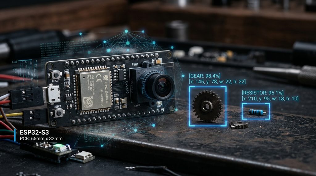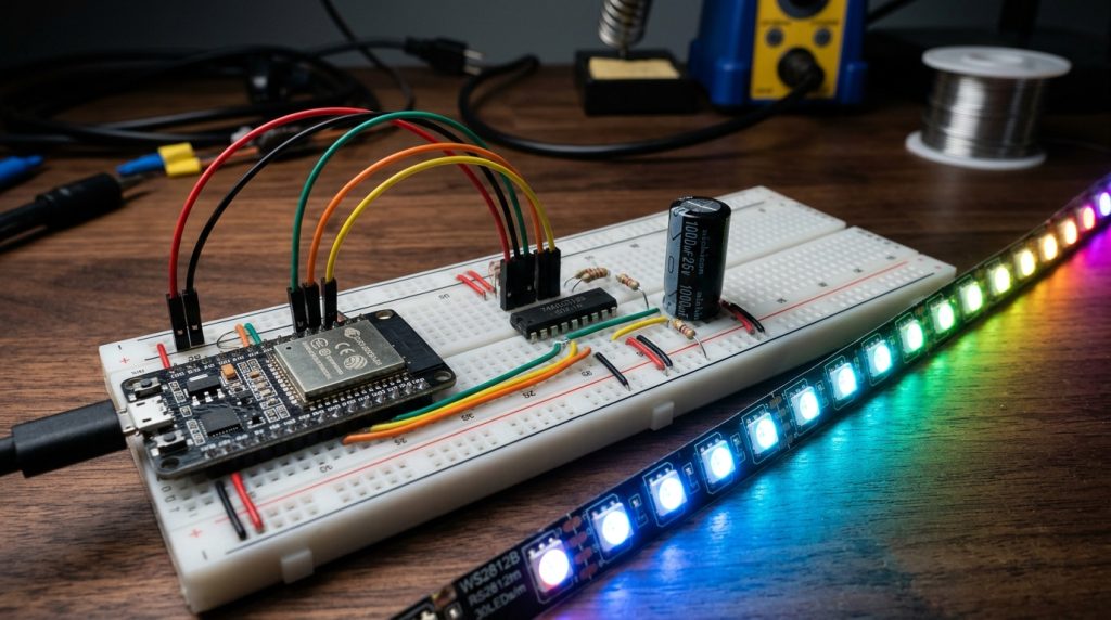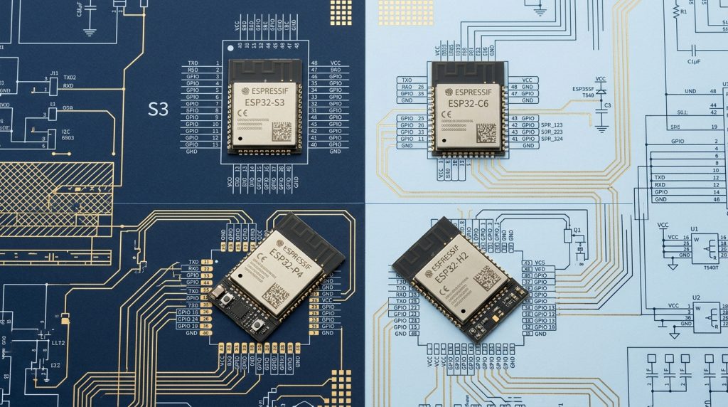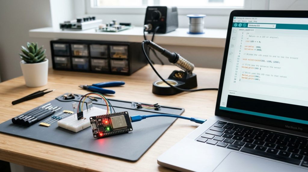
The ESP32 series of microcontrollers by Espressif Systems is the beating heart of modern physical computing and IoT. With dual 32-bit Xtensa cores, built-in Wi-Fi and Bluetooth BLE, capacitive touch inputs, and rich peripheral interfaces, it delivers a massive upgrade over traditional 8-bit Arduino boards at a fraction of the cost.
However, getting started with the ESP32 can occasionally frustrate newcomers due to USB driver conflicts, board manager package versioning, and bootloader synchronization errors (A fatal error occurred: Failed to connect to ESP32: Timed out waiting for packet header). In this comprehensive tutorial, we cover configuring Arduino IDE 2.0+ for the ESP32 from scratch, ensuring seamless code compilation and flashing.
Step 1: Installing USB-to-UART Bridge Drivers
Before your operating system can communicate with the ESP32 over USB, it must recognize the USB-to-UART serial interface chip soldered onto the development board. Flip your ESP32 board over to inspect the small square chip near the micro-USB/USB-C port:
| Interface Chip | Manufacturer | Driver Requirement & Download |
|---|---|---|
| Silicon Labs CP2102 / CP2104 | Silicon Laboratories | Pre-installed on modern Linux/macOS; Windows requires official VCP driver. |
| WCH CH340G / CH340C | Jiangsu Qinheng Microelectronics | Common on budget dev boards; requires CH341SER driver installer. |
| FTDI FT232R | FTDI Chip | Native OS support; update via Windows Update or FTDI VCP drivers. |
| Native USB (ESP32-S2/S3/C3) | Espressif Direct USB/JTAG | No external bridge chip needed; operates via internal USB CDC driver. |
Step 2: Adding Espressif Board Manager URL
Arduino IDE does not include ESP32 definitions out of the box. You must provide the official Espressif package index:
- Open Arduino IDE 2.0+.
- Navigate to File > Preferences (or
Ctrl + ,/Cmd + ,). - Locate the Additional Boards Manager URLs field.
- Paste the official Espressif stable release index URL:
https://espressif.github.io/arduino-esp32/package_esp32_index.json(Note: If you already have other URLs like ESP8266, separate them with a comma).
- Click OK to save your preferences.
Step 3: Installing the ESP32 Core Package
- Open the Boards Manager by clicking the board icon in the left-hand toolbar (or press
Ctrl + Shift + B). - In the search field, type
esp32. - Locate esp32 by Espressif Systems.
- Select the latest stable release (e.g., 3.0.x or 2.0.14+) and click Install.
- Wait 2–5 minutes while the IDE downloads the cross-compiler toolchain, FreeRTOS headers, and hardware libraries.
Step 4: Selecting Your Specific Board and COM Port
Plug your ESP32 into a USB port on your computer:
- Go to Tools > Board > esp32 and select your board model (for standard 30-pin or 38-pin modules, select ESP32 Dev Module; for S3 boards, select ESP32S3 Dev Module).
- Navigate to Tools > Port and select the detected serial communication port (e.g.,
COM3on Windows, or/dev/cu.usbserial-...on macOS). - Set the Upload Speed to
921600for rapid flashing (or drop to115200if flashing over long USB cables).
Step 5: Uploading Your First Test Sketch
Paste this high-performance dual-core diagnostic test sketch into the editor:
void setup() {
  Serial.begin(115200);
  delay(1000);

  Serial.println("=================================");
  Serial.println("ESP32 System Initialization Test");
  Serial.println("=================================");
  Serial.printf("Chip Revision: %d
", ESP.getChipRevision());
  Serial.printf("CPU Frequency: %d MHz
", ESP.getCpuFreqMHz());
  Serial.printf("Flash Chip Size: %d MB
", ESP.getFlashChipSize() / (1024 * 1024));
  Serial.printf("Free Heap Memory: %d bytes
", ESP.getFreeHeap());
  Serial.println("System Ready. Monitoring Loop...");
}

void loop() {
  Serial.printf("Heartbeat: Core %d is running (Uptime: %lu ms)
", xPortGetCoreID(), millis());
  delay(2000);
}
Click the Upload button (Right Arrow icon). Once uploaded, open the Serial Monitor (Ctrl + Shift + M), set the baud rate to 115200, and observe the chip diagnostics!
Troubleshooting: The “Failed to Connect” Bootloader Error
If your upload halts at Connecting........_____....., the auto-reset circuit on your development board has failed to pull GPIO0 LOW during bootloader timing:
- The Manual BOOT Button Trick: When the IDE terminal displays
Connecting........, press and hold down the physical BOOT (or 0) button on your ESP32 board for two seconds until flashing starts (Writing at 0x00010000...), then release it. - The 10uF Capacitor Mod: To permanently fix cheap boards with faulty auto-program circuits, solder a 10uF electrolytic capacitor between the EN (Enable/Reset) pin and GND. This provides sufficient RC delay for the USB DTR/RTS signal to enter bootloader mode automatically.