Connecting a Raspberry Pi running OctoPrint, Klipper (KlipperScreen), or Repetier-Server to your 3D printer via USB is the gold standard for remote monitoring, automated slicing, and telemetry. However, thousands of makers encounter a bizarre and frustrating hardware glitch immediately upon plugging in the USB cable:
- The 3D printer’s LCD screen stays dimly lit or continuously reboots in an endless boot loop—even when the printer’s main 24V/12V power supply switch is turned OFF.
- Connected BLTouch or CR Touch auto-leveling probes deploy their test needles, click frantically, or flash red alarm codes while the machine is powered down.
- When turning on the printer’s main power switch, the motherboard hangs, resets the USB connection, or corrupts EEPROM settings.
This anomaly is not caused by faulty firmware or defective motherboards. It is the direct consequence of parasitic USB 5V backpowering.
The Electrical Cause: The Shared 5V VBUS Rail
A standard USB 2.0 Type-A cable contains four copper conductors:
- Pin 1 (Red / Far Right): +5V Power (VBUS)
- Pin 2 (White): Data Negative (D-)
- Pin 3 (Green): Data Positive (D+)
- Pin 4 (Black / Far Left): Ground (GND)
Most commercial 3D printer mainboards (including Creality v4.2.2/v4.2.7, BigTreeTech SKR, and MKS Robin boards) are designed to be powered either from their main buck converter (converting 24V down to 5V) or directly via USB for convenient bench flashing without a power supply. To save production costs, manufacturers rarely install a reverse-current isolation diode between the USB 5V rail and the motherboard’s internal 5V logic bus.
Consequently, when your Raspberry Pi is powered by its official 5V wall adapter, it pushes current back through the USB cable into the printer’s mainboard. The Raspberry Pi desperately attempts to power the printer’s microcontroller, display backlight, cooling fans, and BLTouch probe. Because the USB port cannot supply sufficient current for all these components, the voltage sags dramatically, causing the display to flicker and the MCU to enter an infinite brownout reset cycle.
Solution 1: The 2-Minute Kapton Tape Mod (Recommended)
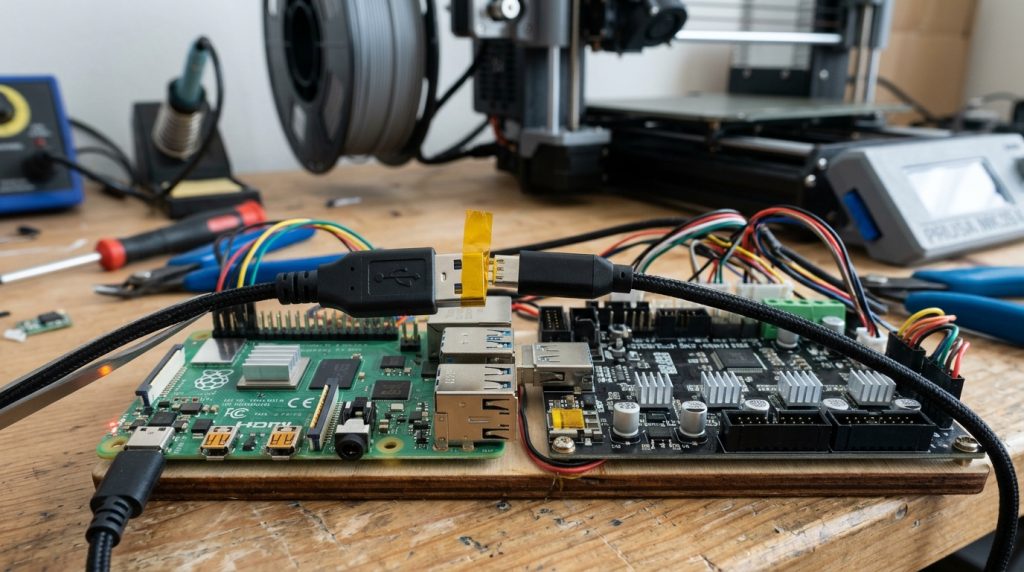
The simplest, completely free, and most reliable permanent fix is to physically insulate Pin 1 (VBUS 5V) inside the USB Type-A connector:
- Inspect the standard USB-A plug that connects to the Raspberry Pi. Hold the plug with the internal plastic tongue facing downward. The four metal contact pins are now visible on top.
- Pin 1 (+5V) is the far-right pin.
- Cut a miniature strip of non-conductive electrical tape (preferably heat-resistant Kapton tape or standard vinyl electrical tape) measuring approximately 1.5 mm wide by 8 mm long.
- Using fine tweezers, place the tape strip over Pin 1 and press it flat. Ensure the tape covers only the far-right contact pin, leaving Data-, Data+, and Ground completely uncovered.
- Plug the cable into the Raspberry Pi. Serial communication continues uninterrupted over D+, D-, and GND, but zero parasitic 5V power can flow into the printer.
Solution 2: Commercial USB Power Blocker (Plug-and-Play)
If you prefer an off-the-shelf hardware solution without modifying cables, install a USB Power Blocker adapter (such as the PortaPow Data-Only adapter). This tiny inline dongle physically severs the +5V trace on a miniature PCB while passing data and ground lines with full impedance matching.
Solution 3: Modifying Custom USB Cables
If you build custom wiring harnesses for enclosure management:
- Strip away 15 mm of outer cable jacket.
- Locate the Red wire (+5V VBUS), snip it cleanly, and insulate both exposed wire ends with heat-shrink tubing.
- NEVER cut the Black wire (GND): High-speed differential USB serial signals strictly require a shared reference ground between the Raspberry Pi and the printer microcontroller. Cutting ground will cause severe communication packet loss and random print halts.
Immediate Verification Checklist
Once you apply the modification, verify proper operation:
- With the printer’s power switch OFF and the Pi running: the printer LCD screen and BLTouch probe must remain completely dark and unpowered.
- Turn ON the printer’s main power switch: OctoPrint connects instantaneously at 115200 or 250000 baud with zero boot loop delays.