When 3D prints suffer from unsightly layer gaps, fragile infill, surface pimples, or dimensional inaccuracy that prevents threaded parts from fitting together, makers often fiddle with print speed or nozzle temperature. However, in more than 85% of cases, the true culprit is volumetric extrusion imbalance. Without proper calibration, your printer simply does not push the precise volume of molten plastic requested by the slicing software.
To achieve pristine, injection-molding quality surface finishes, you must calibrate two distinct layers of the extrusion pipeline: Hardware E-steps (firmware motor rotational accuracy) and Software Flow Rate (filament-specific volumetric compensation).
The Difference Between E-Steps and Flow Rate
Many beginners confuse these two adjustments. Understanding where each parameter lives is the key to consistent results:
- E-Steps (Firmware): Defines how many stepper motor microsteps are required to rotate the extruder drive gears and push exactly 1 mm of raw filament. This is a purely mechanical constant determined by stepper gear ratio, motor degrees per step, and drive gear effective diameter. It should remain fixed once set, regardless of the filament printed.
- Flow Rate / Extrusion Multiplier (Slicer): Compensates for physical material variations, including filament diameter tolerances (1.71mm vs 1.76mm), die swell, and drive gear bite teeth indentation depth. Flow rate varies between filament brands, colors, and polymer types.
Step-by-Step E-Step Calibration Routine
To calibrate your extruder motor steps accurately, follow this physical measurement procedure:
1. Prepare the Filament Mark
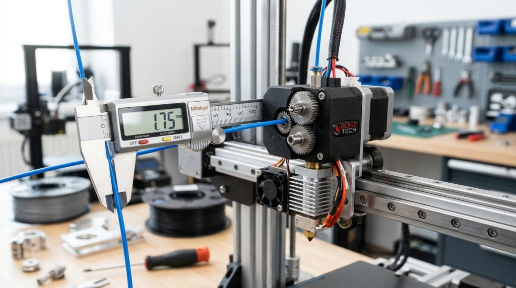
Heat your hotend to your standard filament printing temperature (e.g., 205°C for PLA) to eliminate backpressure resistance. Using a fine-tip permanent marker and a steel ruler or digital calipers, measure exactly 120 mm from the extruder entry point up the raw filament strand and make a crisp mark.
2. Extrude Exactly 100 mm of Filament
Through your printer’s LCD interface, OctoPrint terminal, or Klipper console, issue a slow extrusion command for exactly 100 mm:
M83 ; Set extruder to relative positioning mode
G1 E100 F60 ; Extrude 100 mm at a controlled rate of 60 mm/min (1 mm/s)
3. Measure the Remaining Filament
Once extrusion completes, measure the distance from the extruder entry face to your marker line with digital calipers. In an ideal world, exactly 20 mm should remain (120 mm – 100 mm extruded = 20 mm). If your measured distance differs, your E-steps require adjustment.
4. The Golden Calibration Formula
Calculate the actual length of filament extruded:
Actual Extruded Length = 120 mm - Measured Remaining Distance
Then apply the proportional formula to derive your new step value:
New E-Steps = (Current E-Steps * 100) / Actual Extruded Length
For example, if your current Marlin E-step value is 93.0 and you measure 28 mm of filament remaining (meaning only 92 mm extruded):
New E-Steps = (93.0 * 100) / 92 = 101.08 steps/mm
Save the new value to EEPROM using G-code terminal commands:
M92 E101.08 ; Set new extruder steps/mm
M500 ; Save permanently to EEPROM
For Klipper, update the rotation_distance in printer.cfg:
new_rotation_distance = current_rotation_distance * (Actual Extruded Length / 100)
Calibrating Slicer Flow Rate (Wall Thickness Test)
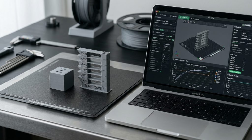
With hardware E-steps mechanically verified, slice a 30x30x30mm hollow test cube with:
- 0% Infill
- 0 Top Layers
- 1 Single Perimeter Wall (e.g., exactly 0.40 mm external perimeter width in slicer settings)
Print the cube and measure the wall thickness on all four sides at mid-height using digital calipers. Average the four readings:
New Flow % = (Target Wall Thickness / Measured Average Thickness) * Current Flow %
If your target is 0.40 mm and you measure an average of 0.43 mm, your printer is over-extruding by 7.5%. Lower your slicer flow rate from 100% to 93% for that specific filament spool to achieve perfectly dimensional prints.